Upload a Code in Ecu Using Can
Ever heard of CAN-BUS merely don't exactly know what it does? Fret not! Nosotros will be discussing everything about CAN-BUS today. I hope that yous'll get a better understanding of information technology through this web log:
- Introduction to CAN Omnibus
- Why utilize Tin can Motorbus protocol
- Tin Bus vs OBD2
- Getting started with Can BUS with Arduino
- CAN BUS Projects
Introduction to Can Autobus
What is Tin BUS?
Tin can stands for Controller Surface area Network, it is used to allow microcontrollers and devices to communicate with each other within a vehicle without a host calculator which allows for control and data acquisition. These devices are also called Electronic Control Units (ECU) and they enable advice between all parts of a vehicle.
Today, you can notice upwards to 70 ECUs in a modern car. Tin is a serial communication bus designed for industrial and automotive applications. For example, they are establish in vehicles, farming equipment, industrial environments, etc.
How does Tin can Double-decker works?
The fuel level, door sensors, odometer, and many more parts of a machine have to communicate with each other some how, and Can Omnibus is what they used to exercise that. These CAN compatible components, which are called "nodes" are continued with a 3-string copper wires, with no central router to govern the flow of data. Every node tin can hear the messages of every other node.
Every node has an ID, where the ones with the higher priority ID can have the priority to "talk" first while the others "listen". This is to ensure that there are never two nodes talking at the aforementioned time. The biggest benefit of Tin can Charabanc is to be able to just connect components without having to worry about signal routing.
So, why not use other communication protocols like UART, SPI and I2C?
Compared to other communication protocols like UART, SPI and I2C, using Can Charabanc communication protocol are much more reliable equally they are standard automotive advice protocols that are used to transmit vital data like a throttle position in a vehicle. If miscommunication or loss of data occurs, information technology could lead to critical failures.
In a vehicle, condom and reliability are the ii most valued features. CAN Motorbus are therefore the ideal protocols for vehicular usage.
The role of Tin can
What will happen if in that location is no CAN in the machine?
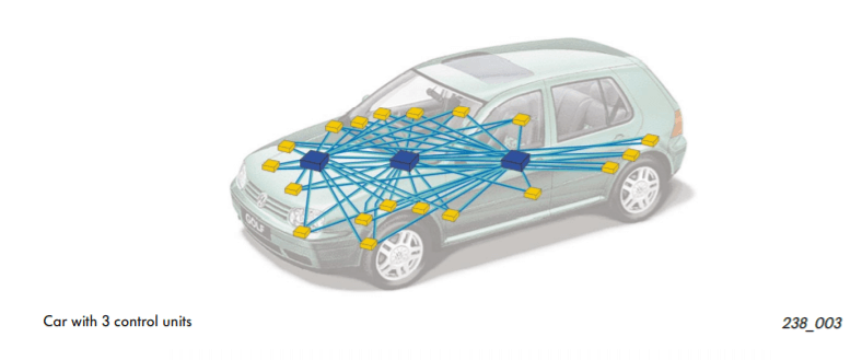
Without CAN BUS protocol, electronic modules in vehicles will have to communicate with each other using direct, betoken-to-betoken analog signal lines. With each module requiring a directly line connected for communication, not only is it time-consuming, it will exist messy with all the excessive amount of wiring as seen on the picture in a higher place. And there may exist unreliable communication between devices. Excessive wires may require additional equipment, which besides creates cost issues.
What about a car with CAN?
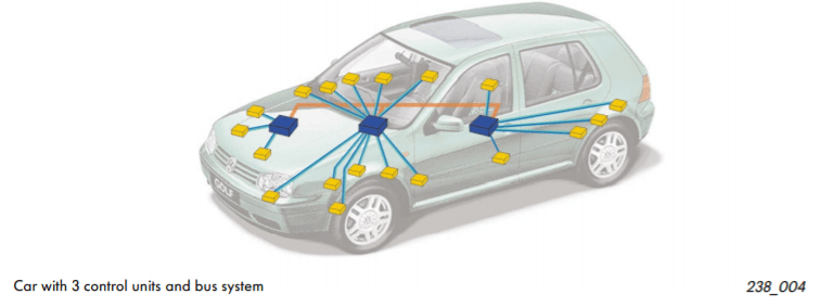
With CAN BUS protocol, information technology eliminates the need of all these wirings by enabling electronic devices to communicate with each other with a single multiplex wire that connects each node in the network to the primary dashboard as seen on the picture above.
The multiplex wire and architecture enable signals to exist combined and transmitted over the entire network with merely a single wire while ensuring each electronic module in vehicles receives information from sensors and actuators. This allows the user to be able to connect any number of ECUs in your vehicle through the ii-wire double-decker.
Information technology also allows for several features to exist added via merely software. Furthermore, an ECU is able to apply data from another ECU which eliminates the need to install the same sensors in multiple devices.
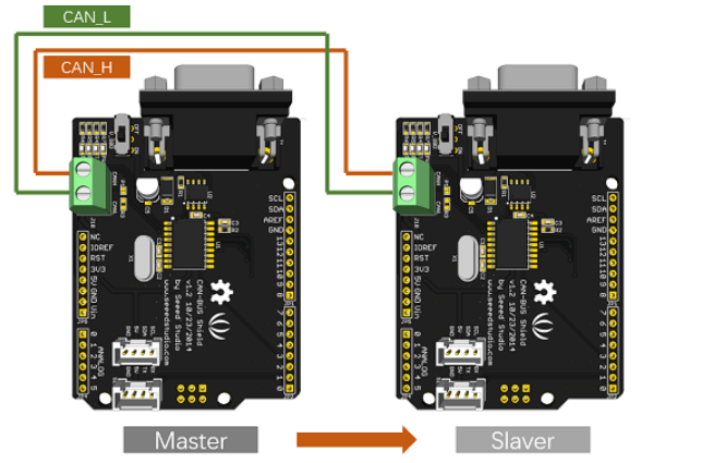
CAN BUS Wiring Sequence
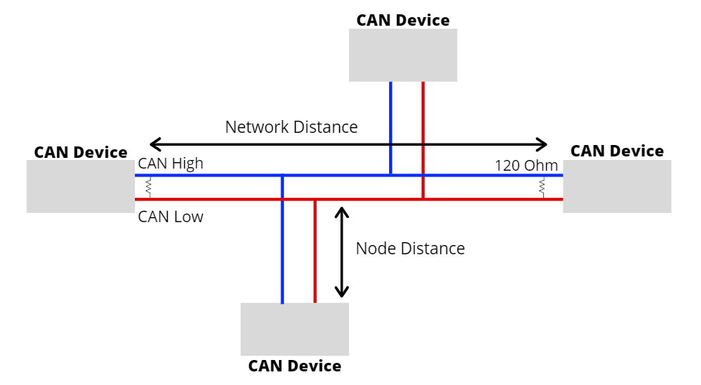
- The Tin BUS protocol consists of two wires for bi-directional information transmission every bit shown in a higher place which are
- CAN_H (CAN Loftier)
- CAN_L (CAN Low)
- The wires deed as a differential line which means the CAN signal either 0 or 1, can be represented by the potential difference between the two wires
- For case, if the difference is positive and large than a certain minimum voltage = one. If the difference is negative = 0
- For Tin termination, as yous tin can come across from the pic above, a single 120 Ohm is generally used at the 2 ends of the Can network.
Tin can BUS Protocol Speed and Range
- Advice speeds of the CAN Charabanc protocol ranges from 10kpbs to 1Mbps.
- The speed also depends on the length of wire used. The shorter it is, the faster the communication speed and the longer information technology is, the slower the communication speed.
- For instance, at 40 meters, the speed will be at 1Mbps. At 1000 meters, the speed can be at 50kpbs.
- The node distance is generally advised to be no more than 0.3 meters / 1 human foot.
CAN Message
- To fully sympathise how the CAN BUS protocol works, permit usa expect at the frames sent over the network.
- The CAN bulletin contains many segments. The ii main segments, identifier and data, will be the ones transmitting the data.
- The identifier is used to identify CAN devices in a Tin network while data will be the sensor or command information that accept to be sent from one device to another.
- The identifier or Tin can ID is either xi or 29 $.25 in length depending on the type of Tin can protocol used.
- Standard Tin can = eleven flake
- Extended CAN = 29 Can
- While the information tin can be anywhere from 0 to 8 bytes.
Why use Tin Motorbus protocol?
Tin can BUS protocol is widely used thank you to the following advantages:
Low Cost
- ECUs communicate via a single CAN interface compared to, for example, direct analog signal lines that reduce errors, weight, and costs.
- With its multiplex wiring that combines analog and digital signals and their transmission over a shared medium, information technology reduces the amount of wiring needed.
- When adding or reducing some equipment, it can be easily operated, and there is no need to carry out large-calibration transformation of the system, which saves a lot of manpower.
Centralized
- Equally CAN Passenger vehicle supports centralized control over electronic devices that are connected to the network, it allows for cardinal mistake diagnosis and configuration across all ECUs
- Fault handling is besides built into the Can protocol where nodes tin can cheque for errors in transmission while maintaining its own fault counter. For example, the protocol supports different error detection capabilities such as bit error, ack mistake, form mistake, CRC error, etc.
Flexible
- As each CAN connected ECU tin receive all transmitted messages, it can too decide whether information technology is relevant and act accordingly.
- The CAN Bus protocol is also a message-based communication protocol where nodes on the bus accept no identifying information.
- With the above features, nodes can hands exist added or remove and modified.
- For beginners, it will be like shooting fish in a barrel to integrate new electronic devices into the Can BUS network without any significant programming overhead.
Robust
- When choosing a advice protocol, immovability and reliability are very important. Y'all would want your communication protocol to be cocky-sustaining and durable for a long period of time without maintenance.
- With the Tin can BUS, the system is robust towards electrical disturbances and electromagnetic interference which makes information technology platonic for vehicles.
Efficient
- Can messages frames are prioritized by ID where the top priority will get bus access and still frames would non exist interrupted.
- Due to wink programming, information technology also saves fourth dimension together with less and simple wiring.
Tin BUS vs OBD2
I am pretty sure you will come up across other "higher-layer protocols" that are related to Tin can BUS like OBD2 BUT they are not the aforementioned!
- The CAN standard does not specify how to handle messages larger than 8 bytes or how to decode the raw data. Therefore, a fix of standardized protocols are adult to further specify how data is communicated between ECUs of a given network and OBD2 is one of them.
- OBD which stands for on-board diagnostics is your vehicle congenital-in self-diagnostic organisation. OBD2 can apply 1 of (many) different coach systems to transfer diagnostic data from and to your automobile.
- I simple analogy I would utilize to differentiate between ii of them will exist OBD2 is like a linguistic communication that we speak where we apply CAN as a communication device like a telephone to talk to someone which in this case a vehicle and its land of health.
- To read more near OBD2, you tin can check out the Wiki Page on OBD.
Explore Seeed's CAN BUS products!
Here at Seeed, we offering a variety of Tin BUS products for your project needs! As shown below:
Tin-Motorcoach Shield V2 ($24.50)
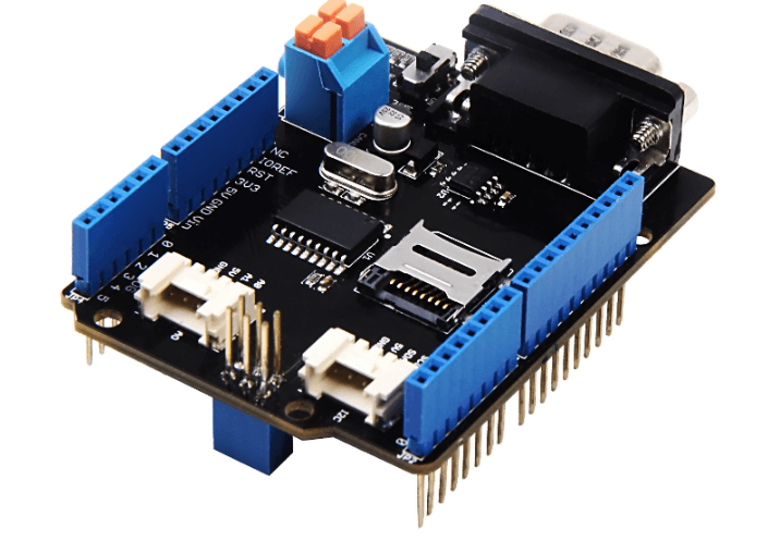
This Tin-BUS Shield adoptsMCP2515 CAN Bus controller with SPI interface andMCP2551 CAN transceiver to give your Arduino/Seeeduino Tin-Bus adequacy. With anOBD-II converter cable added on and the OBD-2 library imported, you are ready to build an onboard diagnostic device or information logger.
To make this Tin can BUS shield convenient to interact with cars, it has an MCP2515 Tin can-Motorcoach controller with SPI interface and MCP2551 Can transceiver to give you lot Arduino/Seeeduino CAN-Jitney capability.
Features of this Tin can Omnibus shield includes:
- Implements Can V2.0B at up to one Mb/s
- Industrial standard 9 pin sub-D connector
- OBD-Ii and Tin standard pinout selectable.
- Changeable chip select pin
- Changeable CS pin for TF menu slot
- Changeable INT pin
- Screw terminal that easily to connect CAN_H and CAN_L
- Arduino Uno pivot headers
- 2 Grove connectors (I2C and UART)
- SPI Interface up to ten MHz
- Standard (11 bit) and extended (29 bit) data and remote frames
- 2 receive buffers with prioritized message storage
CANBed – Arduino Tin can-BUS Development Kit (Atmega32U4 with MCP2515 and MCP2551) ($14.ninety)

CANBed – Arduino CAN-BUS Development Kit carries an Atmega32U4 flake and MCP2515, MCP2551 CAN-BUS controller and transceiver to realize the Can-Autobus advice protocol on a single lath without other MCU to control, it is a Can-Jitney Evolution Board itself! Compared to the above CAN Motorcoach shield, this CAN BED carries an Arduino chip – Atmega32U4 which means it is a combination of the CAN-BUS Shield and Arduino Development Lath together on one single board.
Features of the CANBED includes:
- Atmega32U4 with Arduino Leonardo bootloader on the board
- MCP2515 Can Bus controller and MCP2551 Tin Bus transceiver
- BD-Ii and CAN standard pinout selectable at the sub-D connector
Series Tin-BUS Module based on MCP2551 and MCP2515 ($xiv.90)

If your project is infinite express, hither is a Serial Tin-BUS module which has the full features of Can Bus. The Serial CAN-BUS provides your Arduino or other MCU with the capability of advice to Can Charabanc, such as hacking your vehicle. This Grove Tin can-Coach module is controlled past UART, which means if your MCU has a UART interface, this serial Tin can BUS is available.
Features of this Serial Can Jitney module includes:
- UART to CAN-Bus advice
- AT command
- Upward to 115200 UART baud rate (default 9600)
- Up to 1Mb/s CAN-BUS baud rate
- TX and RX led indicator
- 4pin Grove connector
- 3.3V working voltage
- Easy-to-apply Arduino library
- Modest size
CANBed FD – Arduino Can-FD Development Kit ($17.ninety)

The newest add-on to the Tin family, this CAN Bed-FD carries MCP2517FD Tin can Bus controller with SPI interface and MCP2542FD Can transceiver to attain the Tin can-BUS capability. There is also an ATmega32U4 with Arduino Leonardo bootloader on the board, which allows for easy programming using Arduino IDE. Moreover, there is an OBD-2 converter cablevision added on along with OBD-2 library imported, you're able to build an onboard diagnostic device whenever you feel similar it! Not just that, but Tin can Bed-FD comes in a compact size of 56x41mm which for like shooting fish in a barrel storage and suitable for small projects
Features of the CANBed-FD includes:
- Wide ability input range from 7-28V
- 2 x 4-Pin Grove connectors uniform with the Grove ecosystem
- OBD-Two and CAN standard pinout selectable at the sub-D connector
- Industrial standard 9 pin sub-D connector or 4-pin concluding
- Piece of work at CAN-FD and CAN 2.0
- SPI Interface up to 10 MHz
OBD-2 CAN Bus GPS Development Kit($29.xc)

If you desire to record the GPS log at the aforementioned time, this OBD-II CAN Bus GPS Development Kit is highly recommended! The lath can be plugged directly into the car via the ODB-II interface and supports Arduino programming. The baseboard of the development kit is integrated with an Atmega32U4 microprocessor. The CAN-Motorbus library is available to write sketches using Arduino IDE to send and receive messages from the Can coach network and also allows you to fetch useful information from the messages.
Getting started with Can BUS with Arduino
Getting Started with Can BUS can be very fulfilling. Information technology can exist daunting as well, but this guide will provide you a step-by-footstep guide to become started!
What do y'all demand?
- 2 x Seeeduino V4.2
- 2 ten Tin-Bus Shield V2
- 2 x Jumper Wire\
Instructions
Pace 1: Hardware Connection
- Firstly, connect each Can-BUS shield into Seeeduino V4.2 and connect the 2 CAN-BUS shield together via 2 jumper wires as shown beneath. (CAN_H to CAN_H and CAN_L to CAN_L)
Stride 2: Setting up Software
- Download the library for CAN Omnibus hither and install the library to Arduino IDE after the download has completed.
- If you practice non know how to install an Arduino library, you tin can follow the instructions here.
- One of the nodes (a node means Seeeduino + CAN_BUS Shield) acts as master, the other acts every bit a slaver. The primary will send data to slaver constantly.
- Open the transport example (File > Examples > CAN_BUS_Shield-master >send) and upload to theprincipal as shown below:

- After that, Open thereceive_check instance (File > Examples > CAN_BUS_Shield-principal > receive_check) and upload to theslaver equally shown below

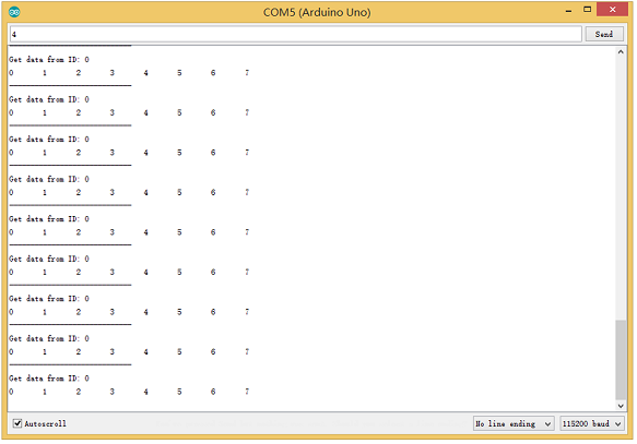
Step 3: View Results
- Open the Serial Monitor of Arduino IDE (slaver), you volition get the information sent from the primary. Below is a photograph of what it volition look like:
Step four: APIs (Application Program Interface)
For the APIs of this software, you tin:
Set the Baud Charge per unit
- This function is used to initialize the baud charge per unit of the CAN Bus system. The available baud rates are listed as follows:
#define CAN_5KBPS 1 #ascertain CAN_10KBPS 2 #define CAN_20KBPS 3 #define CAN_25KBPS 4 #define CAN_31K25BPS v #ascertain CAN_33KBPS 6 #define CAN_40KBPS 7 #define CAN_50KBPS 8 #define CAN_80KBPS 9 #ascertain CAN_83K3BPS ten #define CAN_95KBPS xi #define CAN_100KBPS 12 #define CAN_125KBPS 13 #define CAN_200KBPS 14 #define CAN_250KBPS 15 #define CAN_500KBPS sixteen #ascertain CAN_666kbps 17 #define CAN_1000KBPS xviii Set Receive Mask and Filter
- At that place are 2 receive mask registers and5 filter registers on the controller chip that guarantees you lot getting data from the target device. They are useful especially in a big network consisting of numerous nodes.
- We provide 2 functions for you to utilize these mask and filter registers. They are:
Mask
init_Mask(unsigned char num, unsigned char ext, unsigned char ulData); Filter
init_Filt(unsigned char num, unsigned char ext, unsigned char ulData); - num represents which annals to use. Y'all can fill 0 or 1 for mask and 0 to five for the filter.
- ext represents the status of the frame. 0 means information technology's a mask or filter for a standard frame. 1 ways information technology's for an extended frame.
- ulData represents the content of the mask of the filter.
Check Receive
- The MCP2515 can operate in either a polled style, where the software checks for a received frame, or using additional pins to point that a frame has been received or transmit completed.
- Use the post-obit function to poll for received frames:
INT8U MCP_CAN::checkReceive(void); The function volition return one if a frame arrives, and 0 if nothing arrives.
Get Tin can ID
- When some information arrive, you can utilize the following function to go the Tin ID of the "ship" node.
INT32U MCP_CAN::getCanId(void) Send Data
CAN.sendMsgBuf(INT8U id, INT8U ext, INT8U len, data_buf); It is a function to send data onto the bus. In which:
- id represents where the data comes from.
- ext represents the condition of the frame. '0' ways standard frame. 'ane' means an extended frame.
- len represents the length of this frame.
- data_buf is the content of this message.
For case, In the 'send' example, nosotros accept:
unsigned char stmp[8] = {0, 1, 2, 3, four, 5, vi, 7}; CAN.sendMsgBuf(0x00, 0, 8, stmp); //send out the message 'stmp' to the bus and tell other devices this is a standard frame from 0x00. Receive Data
- The following function is used to receive data on the 'receive' node:
CAN.readMsgBuf(unsigned char len, unsigned char buf); In conditions that masks and filters have been gear up. This function tin only get frames that meet the requirements of masks and filters.
- len represents the data length.
- buf is where you store the information.
Generate a New BaudRate
We had provided many ofttimes-used baud rates, as shown below:
#define CAN_5KBPS ane #define CAN_10KBPS 2 #ascertain CAN_20KBPS iii #define CAN_25KBPS 4 #define CAN_31KBPS v #define CAN_33KBPS 6 #define CAN_40KBPS 7 #ascertain CAN_50KBPS eight #define CAN_80KBPS 9 #define CAN_83KBPS 10 #ascertain CAN_95KBPS 11 #define CAN_100KBPS 12 #define CAN_125KBPS 13 #ascertain CAN_200KBPS 14 #ascertain CAN_250KBPS 15 #define CAN_500KBPS 16 #ascertain CAN_666KBPS 17 #define CAN_1000KBPS eighteen Yet y'all may still can't observe the rate you want. Hither we provide software to help you to calculate the baud rate you demand.
Click here to download the software, information technology'southward in Chinese, but it'south easy to use. Hither is the interface translated for easier usage:

- Open the software, what yous need to do is to set the baud rate you desire, and so practice some simple setting, then click calculate.
- Then you will get some data, cfg1, cfg2 and cfg3.
- You demand to add together some code to the library.
- Open mcp_can_dfs.h, yous demand to add below lawmaking at virtually line 272
#define MCP_16MHz_xxxkBPS_CFG1 (cfg1) // xxx is the baud rate you need #define MCP_16MHz_xxxkBPS_CFG2 (cfg2) #ascertain MCP_16MHz_xxxkBPS_CFG3 (cfg2) - Then allow's get to well-nigh line 390, add beneath code:
#define CAN_xxxKBPS NUM // thirty is the baudrate you lot need, and NUM is a number, you need to go a unlike from the other rates. - Open mcp_can.cpp, goto the part mcp2515_configRate(at about line 190), so add beneath lawmaking:
instance (CAN_xxxKBPS): cfg1 = MCP_16MHz_xxxkBPS_CFG1; cfg2 = MCP_16MHz_xxxkBPS_CFG2; cfg3 = MCP_16MHz_xxxkBPS_CFG3; break; That'south all! Now, you tin can use the baud rate you need!
At present that you've learnt how to interface Tin can BUS with the Arduino using the CAN BUS shield, here are some CAN Bus projects to become you lot started!
CAN Autobus Projects
Volkswagen Tin can Motorcoach Gaming
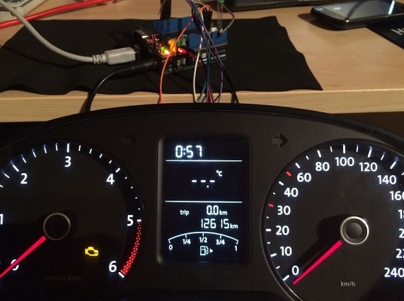
E'er wanted to play a auto/truck simulator with a real dashboard on your PC? With the CAN BUS shield, you can! In this projection, I'one thousand trying to control a VW Polo 6R dashboard via CAN Bus with an Arduino Uno and a Seeed Tin can Bus Shield.
What you lot'll need:
- Seeeduino V4.2 / Arduino UNO Rev3
- Can-Bus Shield V2
- Jumper Wires
- Blazon-B USB cable for Arduino Diecimila and Freeduino
Interested? Y'all tin can check out the full tutorial at SeeedStudio Community!
Hacking your Vehicle
Modernistic Vehicles all come equipped with a Tin can-Autobus Controller Area Network, Instead of having a one thousand thousand wires running back and forth from various devices in your motorcar to the battery, its making use of a more than clever system. From each node (IE Switch pod that controls your windows or electric door locks) it broadcasts a message across the Can. When the TIPM detects a valid message it will react accordingly like, lock the doors, switch on lights so on. With the CAN BUS shield, you tin now hack your vehicle!
What practice you demand?
- Seeeduino V4.2 / Arduino UNO Rev3
- CAN-Charabanc Shield V2
- Jumper Wires
Interested? You can observe the total tutorial past mvilijoen2 on Instructables!
Summary
With the basic knowledge of CAN Motorbus protocol in your hands, one way that you can utilise it is to clarify the data/letters passing through your vehicle and also hack your vehicle!
I promise you learn more than about the CAN-Motorbus protocol in this guide! If you have whatsoever questions regarding CAN BUS, feel gratis to drop a comment down in the comment section down beneath.
Interested in more CAN Coach products? Yous can bank check out all of our CAN BUS products hither!
Tags: Advantage of using Tin can Motorbus, Arduino Tin can BUS, Can Jitney, Tin Charabanc Message, CAN Bus Projects, CAN Motorbus Protocol, CAN Double-decker Protocol Range, CAN Charabanc Protocol Speed, CAN BUS Organisation, CAN BUS vs OBD2, CAN Omnibus Wires, CAN Protocol, Tin can-Jitney Shield, Introduction to CAN BUS, OBD2, Tutorial
Source: https://www.seeedstudio.com/blog/2019/11/27/introduction-to-can-bus-and-how-to-use-it-with-arduino/
Post a Comment for "Upload a Code in Ecu Using Can"